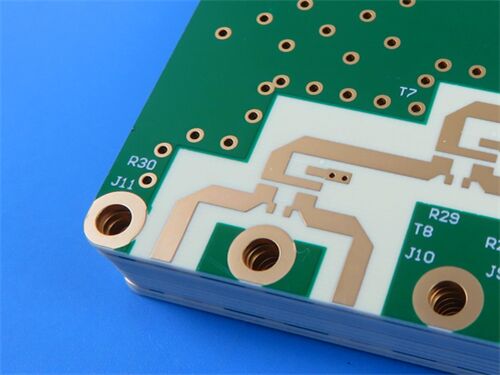
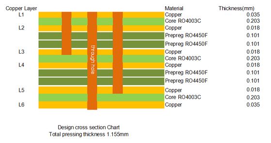
Этот ПХБ представляет собой 6-слойную медную структуру, и его материалный состав в основном включаетRO4003CЯдро, препреграмма RO4450F и медная фольга.
Подробная информация о ПКБ
| Спецификация |
Подробная информация |
| Структура слоя |
Верхний слой (0,203 мм RO4003C) + 2PCS RO4450F Prepreg + Средний слой (0,203 мм RO4003C) + 2PCS RO4450F Prepreg + Нижний слой (0,203 мм RO4003C) |
| Толщина меди |
Внешний слой (L1, L6) - 1 унция готовой меди (0,035 мм); Внутренний слой (L2-L5) - 0,5 унции готовой меди (0,018 мм) |
| Толщина прессования |
1.155 мм |
| Обработка поверхности |
Верхний и нижний слои с зеленой маской сварки и белым шелковым экраном; Золото погружения |
| Размер |
92.5 мм × 77,3 мм (1 PCS) |
| Специальный процесс |
Задняя бурение (L1-L3, L1-L5) |
ПХБ-накопление
| Слой No. |
Описание |
Толщина |
| 1 |
Медный слой L1 (Внешний верх, 1 унция готовой меди) |
0.035 мм |
| 2 |
Ядро RO4003C |
0.203 мм |
| 3 |
Медный слой L2 (Внутренний слой, 0,5 унции готовой меди) |
0.018 мм |
| 4 |
Препрег RO4450F |
0.101 мм |
| 5 |
Препрег RO4450F |
0.101 мм |
| 6 |
Медный слой L3 (Внутренний слой, 0,5 унции готовой меди) |
0.018 мм |
| 7 |
Ядро RO4003C |
0.203 мм |
| 8 |
Медный слой L4 (внутренний слой, 0,5 унции готовой меди) |
0.018 мм |
| 9 |
Препрег RO4450F |
0.101 мм |
| 10 |
Препрег RO4450F |
0.101 мм |
| 11 |
Медный слой L5 (Внутренний слой, 0,5 унции готовой меди) |
0.018 мм |
| 12 |
Ядро RO4003C |
0.203 мм |
| 13 |
Медный слой L6 (Внешнее дно, 1 унция готовой меди) |
0.035 мм |
| Общая толщина прессования |
1.155 мм |

Что такое Back Drill?
Back drilling (Back Drilling) - это специальный процесс бурения, используемый при производстве высокоскоростных и высокочастотных ПКБ,с непроводящей частью избыточного медного столба (называемого "стоп") в проходном отверстии, чтобы значительно улучшить целостность передачи сигнала.
В многослойных печатных пластинках сигнальные линии, соединяющие различные слои, обычно используют прокладки, которые обычно проникают по всей толщине печатного пластинки.Когда сигнал передается из одного слоя (например, слоя 1) в целевой слой (например, слой 3 или слой 5) через, часть через ниже целевого слоя (протягиваясь до нижних слоев) не имеет функции электрического соединения, и этот избыточный медный столб является "стоп". при высоких скоростях или высоких частотах,Ключ похож на короткую антенну., что вызовет серьезное отражение сигнала, что приведет к искажению сигнала, смещению времени, закрытию диаграммы глаз и даже кодам ошибок системы или отказу.
Процесс обратного бурения решает эту проблему с помощью вторичного бурения: после завершения процесса производства обычных ПКБ,сверло с диаметром немного больше, чем оригинал через отверстие используется для бурения сзади или сбоку ПКБ, и глубина бурения точно контролируется, чтобы просто просверлить часть ниже целевого слоя, чтобы физически удалить косточку.оставшаяся стенка отверстия представляет собой непроводимую подложку, которая больше не участвует в передаче сигнала., который может значительно уменьшить отражение и потерю сигнала, улучшить скорость передачи сигнала, уменьшить дрожь и оптимизировать качество сигнала.обратное бурение имеет более высокую эффективность затрат для сценариев, которые требуют высокоскоростных каналов, но не чрезвычайно высоких слоев.
В этом случае на ПКБ применяется обратное бурение в диапазоне L1-L3 и L1-L5, что может эффективно обеспечить целостность сигнала высокоскоростной передачи в ПКБ.
Введение в RO4003C
RO4003C - это проприетарный стеклянный ткань усиленный, керамически наполненный углеводородный композитный материал, разработанный корпорацией Rogers,который сочетает в себе отличные электрические характеристики ПТФЕ/стеклянной ткани и обработку эпоксидной смолы/стеклянной тканиМатериал имеет две различные конфигурации с использованием 1080 и 1674 стеклянных тканей, и все конфигурации имеют одинаковые электрические характеристики.стабильная и постоянная диэлектрическая постоянная (Dk) и характеристики низких потерь, и его уникальные механические свойства делают его таким же, как стандартный процесс обработки эпоксидной смолы/стекла, при этом стоимость намного ниже, чем у традиционных микроволновых ламинатов.В отличие от PTFE микроволновых материалов, этот материал не требует специальных методов обработки или обработки.
Ключевые параметры RO4003C (содержание основных данных)
| Параметр |
Типичная стоимость |
Примечания/Метод испытания |
| Диэлектрическая постоянная (Dk) @10 ГГц |
3.38 ± 0.05 |
Типичное значение процесса; Типичное значение конструкции - 3.55 |
| Фактор потери (Df) @10 ГГц |
0.0027 |
Типичная стоимость с отличными показателями низких потерь |
| Коэффициент теплового расширения по оси Z (CTE) |
46 ppm/°C |
Типичное значение -55°C - 288°C |
| Сопротивляемость объема |
1.7×10¹⁰ MΩ•см |
Типичная величина, хорошие характеристики изоляции |
| Поглощение воды (D48/50%) |
00,04%. |
Типичное значение, отличная влагостойкость |
| Теплопроводность @50°C |
00,71 W/m•°K |
ASTM D5470, хорошие показатели рассеивания тепла |
| Устойчивость к очистке (1 унция ED фольги) |
60,0 фунта/дюйм (1,05 Н/мм) |
Типичное значение, сильная сила связывания с медной фольгой |
| Степень огнеупорности |
Не FR |
Не соответствует стандарту UL 94 V-0 |
| Совместимость процессов без свинца |
Да, да. |
Подходит для сборочных процессов без свинца |
Сферы применения RO4003C
RO4003C пользуется превосходными электрическими характеристиками, обрабатываемостью и экономичностью и широко используется в области микроволнового, высокочастотного и высокоскоростного электронного оборудования.в основном включая:
Коммуникационная инфраструктура: антенны сотовой базовой станции, радиообслуживание, Wi-Fi для телекоммуникаций/авторизованные вспомогательные системы доступа, IP-инфраструктура,и микроволновое оборудование связи точка-точка.
Автомобильная разведка: Автомобильные радиолокационные системы и датчики, поддерживающие развитие технологий автономного вождения и безопасности транспортных средств.
Высокочастотное и высокоскоростное оборудование: Радарные системы фазового массива, усилители мощности, высокоскоростные серверы (CPU/GPU/мемориальная взаимосвязь), высокоскоростное сетевое коммуникационное оборудование (маршрутизаторы,переключатели, оптические модули).
Интернет вещей (IoT): антенны RFID, улучшающие точность идентификации и охват сигнала.
Другие области: испытательное и измерительное оборудование, аэрокосмические и оборонные электронные системы,и другое оборудование, которое должно обрабатывать высокоскоростные цифровые сигналы на уровне Gbps или радиочастотные микроволновые сигналы.

 Ваше сообщение должно содержать от 20 до 3000 символов!
 Russian